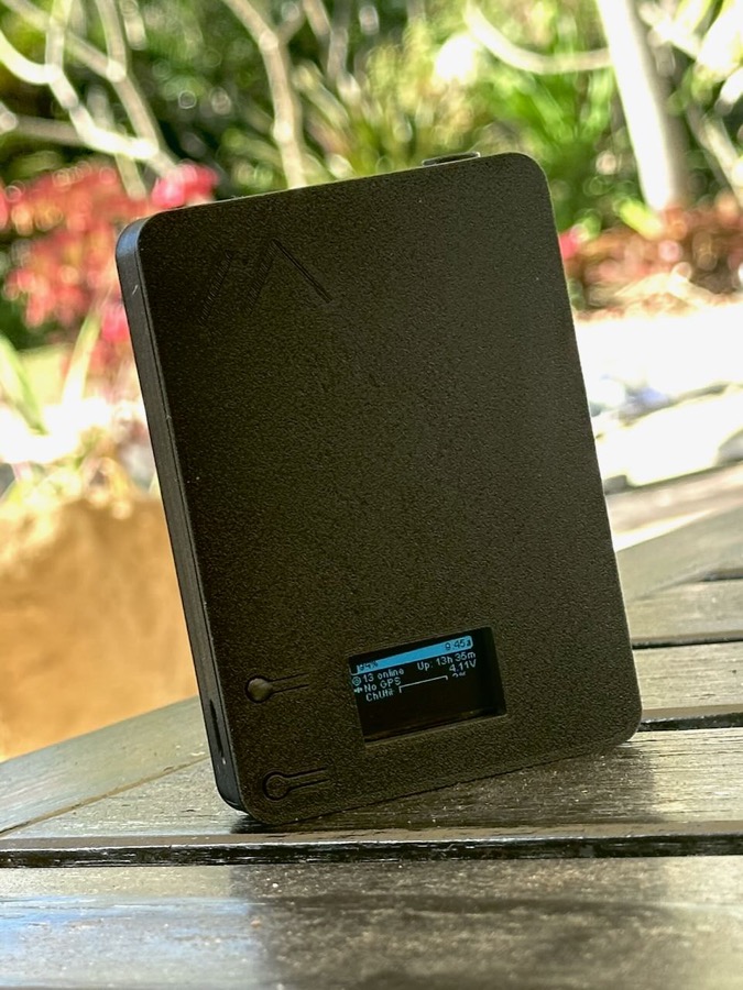
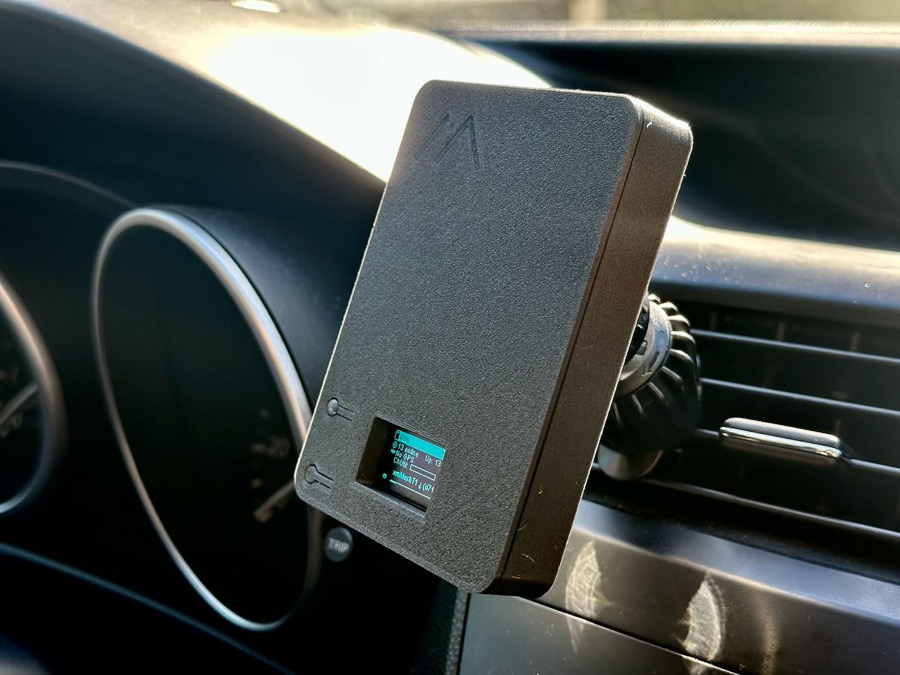
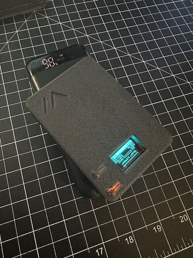
A small and compact 3D printable case design for a Heltec V3 board, 3000mah battery, magsafe magnet ring, 5v wireless charging coil, and internal or external antenna. Designed to be roughly the size of a magsafe booster battery pack, easy to pocket, attach to the back of your phone or use on a car mount. Adding wireless charging requires just 4 easy solder points and uses the built-in power management, exactly the same as plugging in via USB-C.
3D print files available here:
General Disclaimer:
This is a hobby project, I am not a professional product designer or engineer so there are no guarantees that the case will work perfectly for you without modifications. You accept all responsbility if you use these instructions. I designed this around the specific parts that I had but there are definitely small variations in the boards and battery sizes. Note that this is not a waterproof or dustproof design. Free free to take the files and edit or update to fit your own needs, just please don't start selling them, that would be super-ass lame. Be cool my friends.
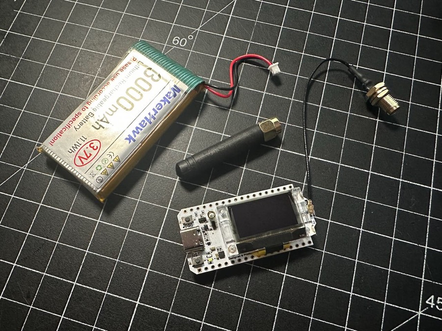
Here is the Amazon link to the specific Heltec combo kit I used which includes the board, battery and extra antenna:
https://a.co/d/4bVTPl1
Printing Tips:
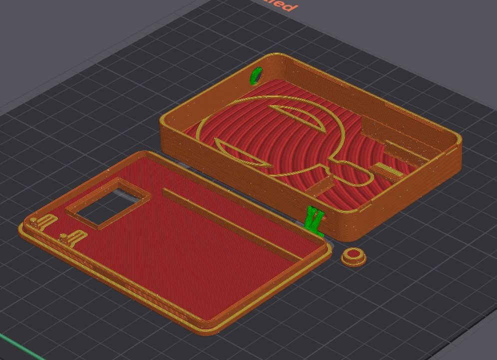
There are three printed parts: main case body, lid, and a plug for the optional external antenna hole. I have printed cases with both PETG and PLA and generally used a 0.2 layer height, 50% infill and 3 wall loops. You will need some very small supports for the main case (shown in green) to properly support the USB-C and antenna holes. Print orientation is very straightforward:
Assembly:
I would recommend reading through the entire instructions before proceeding, so you understand what steps you will be tackling. Generally, all of this is very simple, just take your time.
Here is the parts list for the full case with all the options:
Step 1
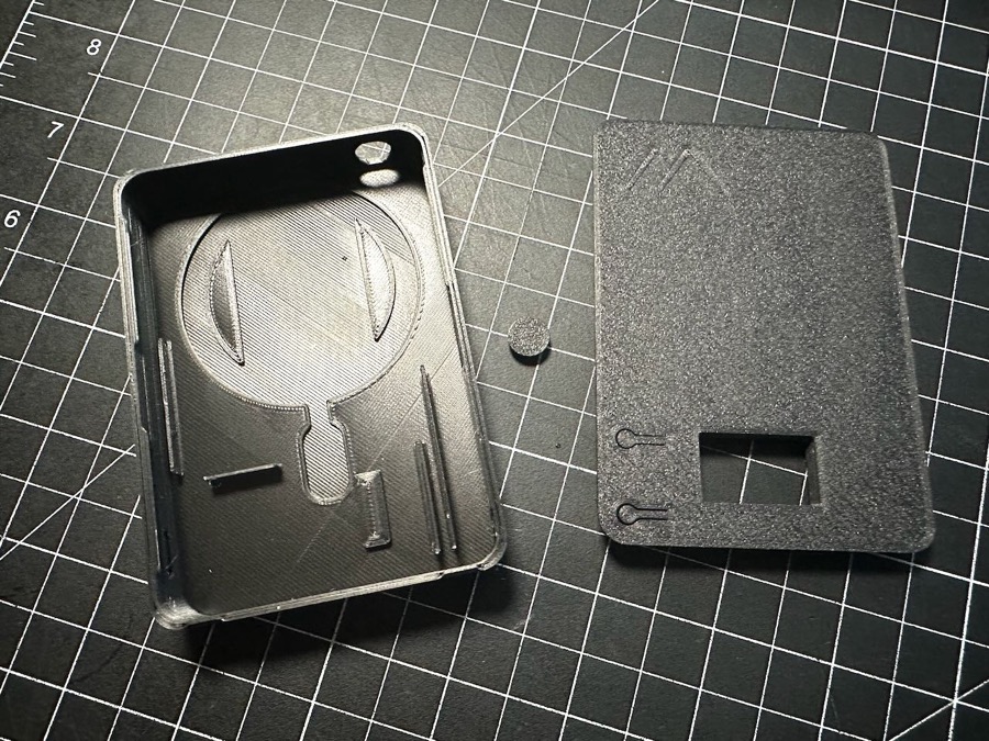
- Ensure that all your printed parts fit together. The case and lid are designed with a tight snap fit.
- To install the lid, angle one long edge with the notches of the case, then press down on the opposite side to snap into place. It may take a firm press to snap it in. Depending on the quality settings of your print and the material you use, those press-fit joints could wear/break with repeated use so avoid unecessary opening of the case..
- There are two small grooves at the bottom of the case that you can use with a spudger/pry tool to remove the lid.
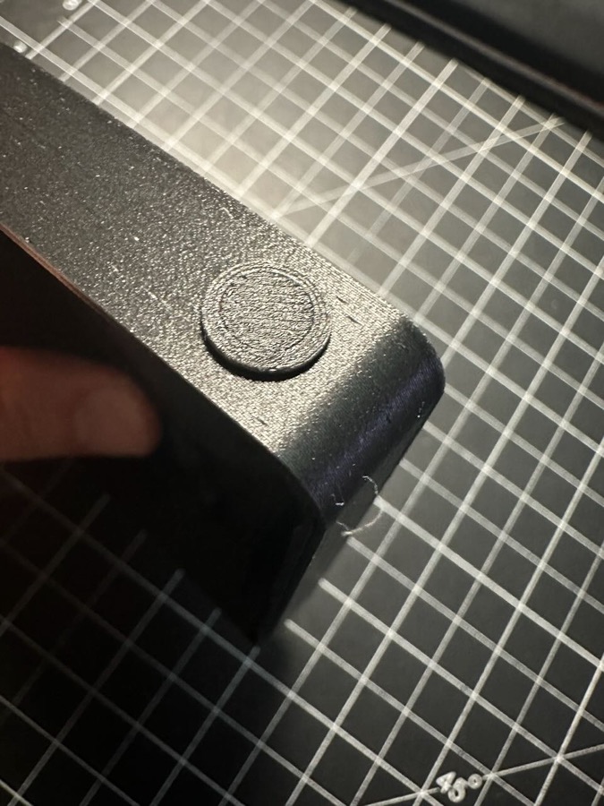
- Make sure the antenna hole is round and you can snap in the plug.
- Depending on your printed supports, you may need to do a little cleanup on the antenna and USB holes with a file or sandpaper.
Step 2
- Decide if you want an internal or external antenna.
- If internal, insert the antenna plug and then add a dab of super or hot glue inside the case just to hold it in place. Don't use too much, in case you want to change to an external antenna later.
- If you plan to use an external antenna, set the plug aside.
Step 3
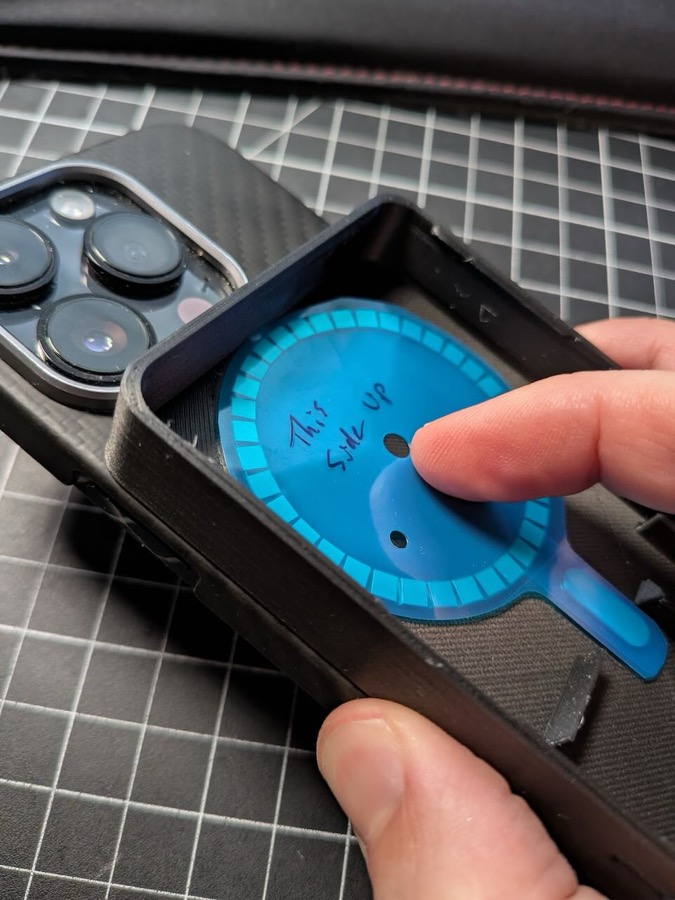
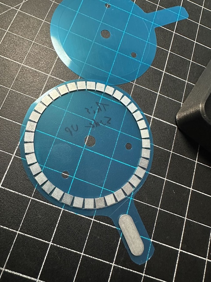
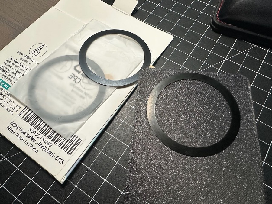
- Before peeling the protective sheet off the magnets, ensure that you have them facing the correct direction.
- Test by temporarily holding the magnets inside the case by hand and trying to attach the case to your phone. One side of the magnet ring will have noticeably stronger holding power.
- Peel off the back side of the protective sheet, carefully position and firmly press the magnets into place.
- If using the wireless charging: Peel off the top protective sheet so that the center area inside the magnet ring is open for placement of the charging coil.
Wireless Charging Option (skip to Step 8 if not using this feature)
Step 4
- Prep the wiring. You will need to do a very small amount of simple soldering to add the charging coil.
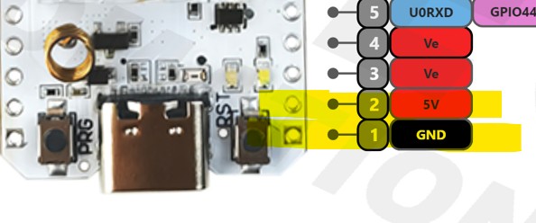
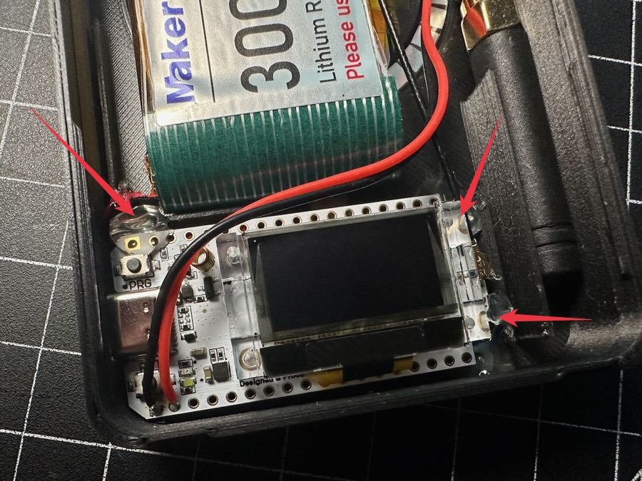
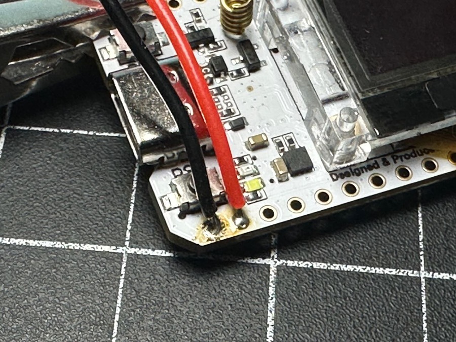
- First, with your Heltec board powered off and disconnected, locate the two GPIO pins which are at the very end of the board on the RST button side.
- Pin 1, all the way at the end is the 5v ground, while Pin 2 right next to it is the 5v power.
- Solder one of your JST 1.25 connectors to those pins, with the black wire to Pin 1 GND and red to the 5v power Pin 2.
- You can use either the male or female cable, one wire will be on the Heltec and the matching one will be on the charger coil.
- Position the wires so they point toward the right running underneath the display so they don't interfere with the RST button. (Picture below has the wires positioned for clearly showing the pin locations)
Step 5
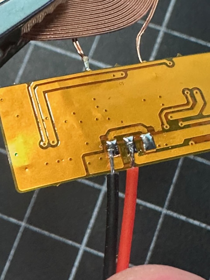
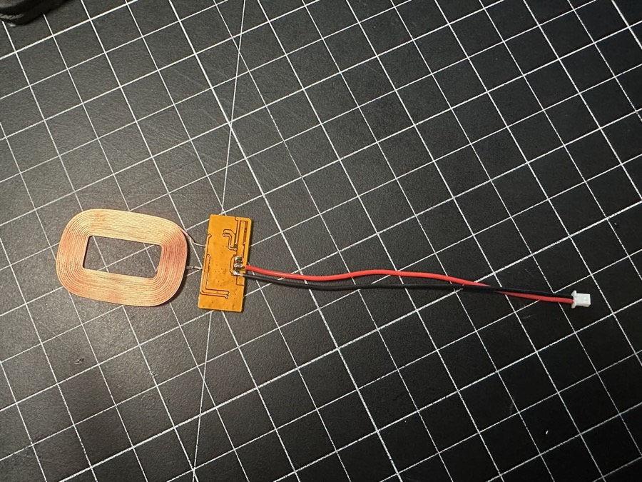
- Similarly, solder the other JST wire to the charging board of the coil. The board might already come with wires attached.
- If so, note which pad is black and red and use your soldering iron to gently remove the original wires.
- As with the wire you added to the Heltec, you want to have the red wire go to + Positive and black to - Negative on the board.
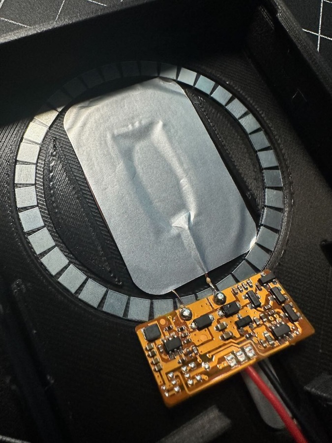
Step 6
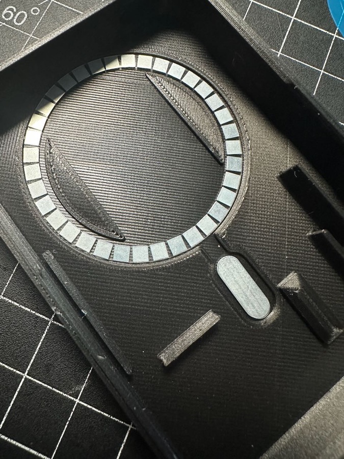
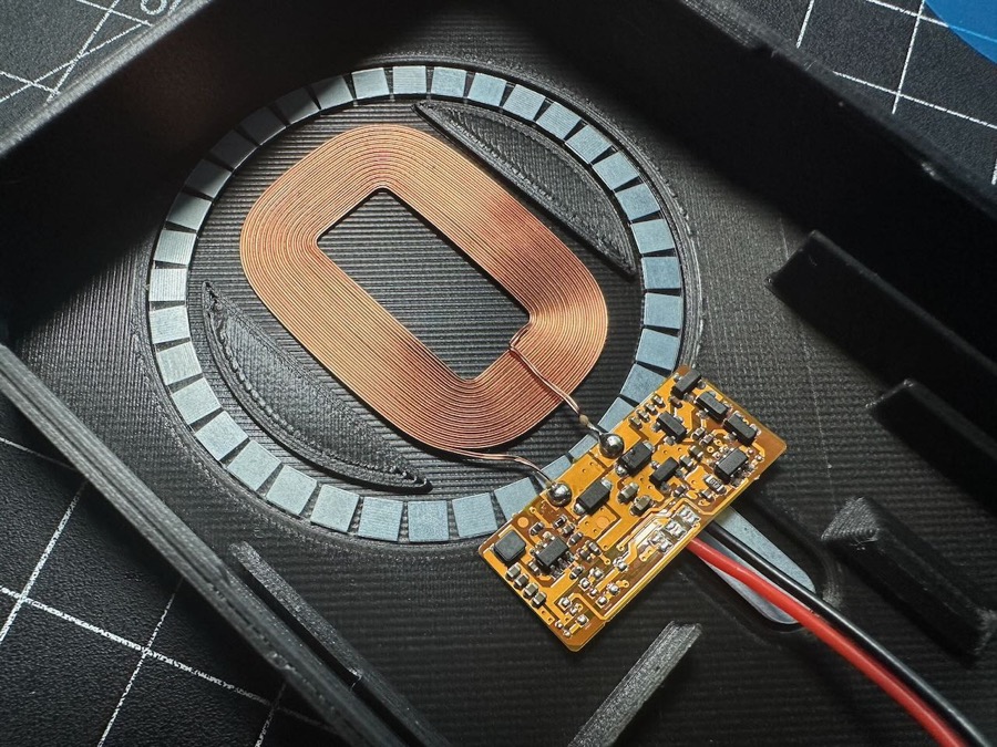
- Position the coil into the space between the raised indentations inside the magnet ring.
- The power board should be below the coil, and make sure that you can see the front of the board PCB (where all the microchips are).
- This will ensure the coil is in the right orientation and will let you flip the board up onto the coil for final installation.
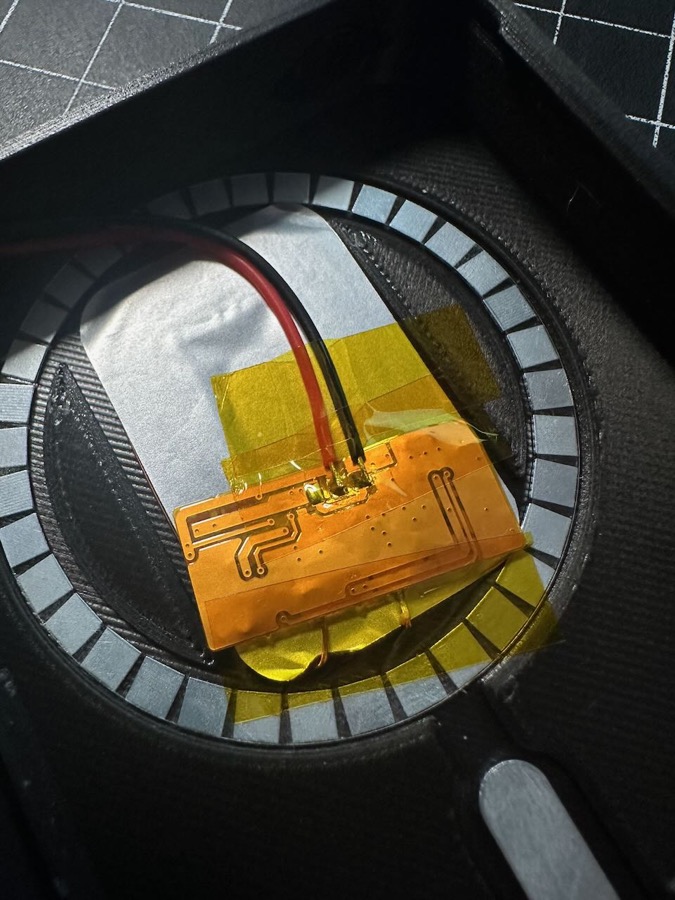
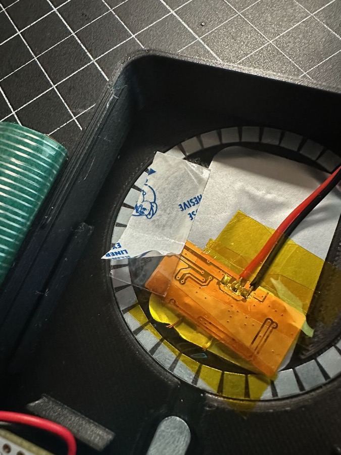
Step 7
- If desired for better aesthetics, prepare the included silver/black isolation layer sticker by rounding the corners of the sticker to match the rounded profile of the coil.
- Place the sticker on top of the coil, pressing firmly to secure the sticker and hold the coil in place.
- Gently flip the board up so that it rests on top of the covered coil. It is recommended to cover the solder points and back of the board with kapton tape.
- Position the JST wires to go up and to the right side of the case.
Step 8
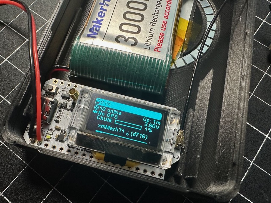
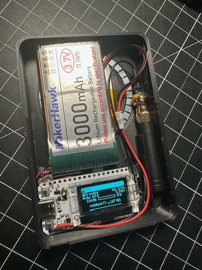
- Attach the antenna cable to the Heltec. Orient the antenna connector to the pointed up to the top of the case.
- Plug the lipo battery into the bottom JST connector on your Heltec. If the board boots up automatically, it's probably a good idea to power it off by holding the PRG button.
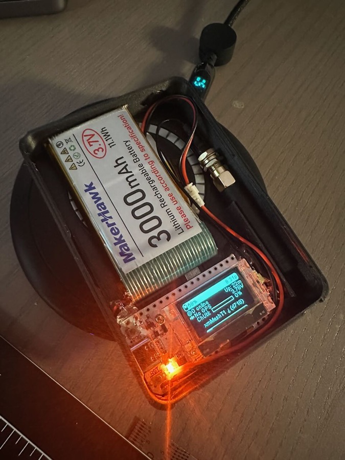
Step 9
Step 10
- Secure the battery with a small piece of double-sided tape placed on the left-side wedge-shape.
Step 11
- If you haven't already, press the antenna into the small channel on the right side of the case if using internal. If external, unscrew the nut from the SMA connector, feed the connector into the hole at the top of the case and secure with the nut.
- If using a different style of internal antenna, you may need to tape/glue it into the space to prevent it rattling around.
Step 12
- Verify operation of charging modes.
- Make sure your board turns on.
- Plug in a USB-C power source to verify charging light turns on.
- With USB-C UNPLUGGED, place unit on wireless charging puck/mat and make sure charging light turns on.
Step 13
- Apply the Magsafe magnet sticker to the outside of the case back for additional holding power.
- You can remove the adhesive backing and then let the internal magnet be the guide to position it, the magnet sticker should basically align itself into place if you hover it over the area
- Press the sticker ring firmly into place.
Step 14
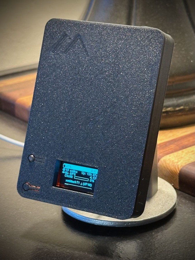
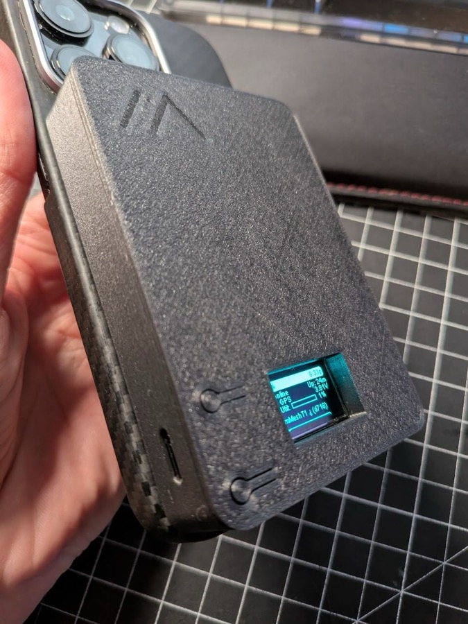
- Snap cover into place and enjoy your new Meshtastic node with magsafe and wireless charging!